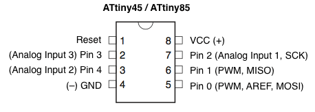
The Attiny85 is a nice little 8 pin chip which is ideal for simple projects, they are low cost and if you have an Arduino you can actually burn the bootloader and upload your sketches to the microcontroller, this is perfect for beginners.
I recommend buying one of the cheap Arduino Uno clones for this task and using it for this purpose.
To program the ATtiny85 we need to first set Arduino Uno as an ISP. Connect your Arduino Uno to the PC. Open the Arduino IDE and open the ArduinoISP example file (File -> Examples -> ArduinoISP) and upload it. If there are no error messages the your Arduino should be good to go.
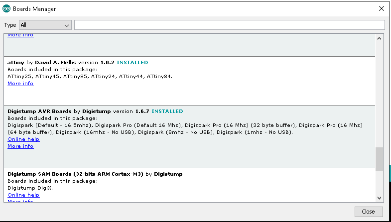
By default the Arduino IDE doesn’t support ATtiny85 but luckily it is quite easy to add ATtiny board support to the Arduino IDE. to do this you simply goto Open File -> Preferences and in the Additional Boards Manager URLs add the following https://raw.githubusercontent.com/damellis/attiny/ide-1.6.x-boards-manager/package_damellis_attiny_index.json. Now go to Tools -> Board -> Board Manager scroll down the list to where it says “attiny by Davis A. Mellis”. Click on that and install it. and you should see the following
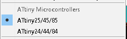
Navigate to the boards menu and you should have some new options, here I have highlighted the option required
Now we will get ready to program our Attiny, we need some parts here as we will building a simple circuit. You can build this on a breadboard
Assembly List
| Label | Part Type | Properties |
|---|---|---|
| C1 | Electrolytic Capacitor | capacitance 10µF; voltage 16V; package 100 mil [THT, electrolytic] |
| LED1 | Red (633nm) LED | color Red (633nm); leg yes; package 5 mm [THT] |
| Part1 | Arduino Uno (Rev3) | type Arduino UNO (Rev3) |
| R1 | 470Ω Resistor | pin spacing 400 mil; bands 4; package THT; tolerance ±5%; resistance 470Ω |
| U1 | ATTINY45 | editable pin labels false; variant dip08; chip label attiny45; package dip |
Layout
In this example we will connect the Attiny to our Arduino and program it, we will also connect an LED which we will use for test purposes
The Arduino to Attiny 85 connections are as follows
ATtiny Pin 2 to Arduino Pin 13
ATtiny Pin 1 to Arduino Pin 12
ATtiny Pin 0 to Arduino Pin 11
ATtiny Reset Pin to Arduino Pin 10
Lets see a breadboard layout of what we will be building

A 10uF capacitor is required between RESET and GND in arduino. This is to avoid the arduino from being auto reset when we upload the program to attiny85. If you are using a electrolytic capacitor make sure the anode of the capacitor goes in GND of the Arduino.
Coding and uploading sketches
Now we are ready to upload a code example to our Attiny. First we have to setup the Arduino IDE as follows
Select ATtiny under Tools -> Board.
Select ATtiny85 under Tools -> Processor.
Select 8 MHz (internal) under Tools -> Clock.
Select Arduino as ISP is selected under Tools -> Programmer.
Select Tools -> Burn Bootloader.
All going well you should see a success message
We then modify the Blink sketch to use pin 4 of the Attiny
[codesyntax lang=”cpp”]
void setup() {
  // initialize digital pin 4 as an output.
  pinMode(4, OUTPUT);
}

// the loop function runs over and over again forever
void loop() {
  digitalWrite(4, HIGH);   // turn the LED on (HIGH is the voltage level)
  delay(1000);              // wait for a second
  digitalWrite(4, LOW);    // turn the LED off by making the voltage LOW
  delay(1000);              // wait for a second
}
[/codesyntax]
Upload the sketch and if there are no errors the LED connected to pin 3 of your Attiny85 should blink on and off and that’s it.