
In this article we look at an another electronic kit, this time its a AT89C2051 based DS18B20 temperature kit.
The kit you get looks like this when bought
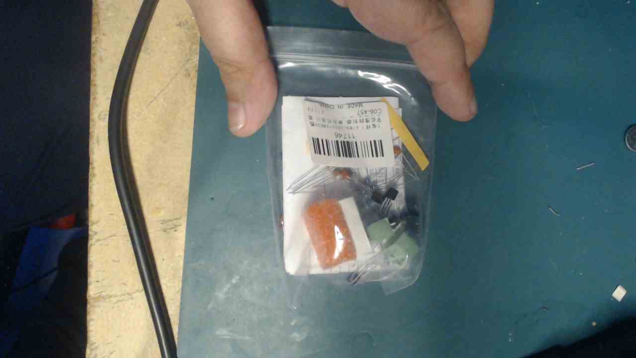
Its an easy kit to assemble as all of the parts are through hole, no SMT parts.
Specs
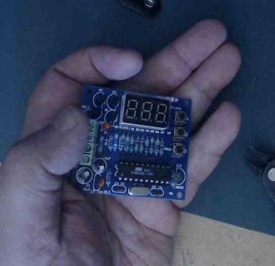
This circuit uses a DS18B20 as temperature sensor;a 3-bit common anode digital tube for display;and it uses a AT89C2051 microcontroller to read the sensor and display the values.
You connect a 5V+/-0.5V DC power on X1 port (please pay attention to positive and negative),
press the S1 button circuit display the current temperature value; if you press the switch again,S1 will enter into temperature set state.
Then you can press S2 or S3 to adjust temperature value;if you then press the S1 switch again,it will come back to current temperature display and save the value at the same time.
This value will be saved in DS18B20,even if the circuit is powered off it will not be lost.
When the circuit is powered on for the next time,the microcontroller will automatically read the previous temperature setting value;long press S1 is for closing the display and temperature control;if press it again,function will be open.
When the current temperature is over the set temperature, the LED will be switched on and there will be 5V on X2 port,and it can drive an external device
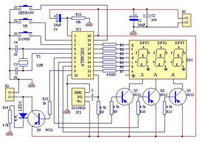
Schematic
You can see some of the microcontroller pins used in the schematic – no source code for this.
You can see that pins 12 – 18 control the segments and pins 6 – 8 drive the individual led
S1 is connected to pin 19 and S2 and S3 are connected to pins 2 and 3 respectively.
The all important DS18B20 is connected to pin 11 of the microcontroller. There is also an LED and 5v output driven from pin 9.
Parts List
| Number | Name | Specification | Quantity |
| R1,R2,R3,R4,R5,R6,R7 | Resistor | 470 ohm | 7 |
| R8,R9,R10,R11,R14 | Resistor | 4.7K ohm | 5 |
| R12 | Resistor | 10K ohm | 1 |
| R13 | Resistor | 1K ohm | 1 |
| C1,C3 | Electrolytic Capacitor | 10uF | 2 |
| C2 | Ceramic Capacitor | 0.1uF | 1 |
| C4,C5 | Ceramic Capacitor | 30pF | 2 |
| Q1,Q2,Q3,Q4 | Transistor | 9012 | 4 |
| Y1 | Crystal Oscillator | 12m | 1 |
| S1,S2,S3 | Button Switch | 6x6x10mm | 3 |
| IC1 | MCU | AT89C2051 | 1 |
| IC Socket | 20P | 1 | |
| IC2 | Temperature Sensor | DS18B20 | 1 |
| DS1 | Digital Tube | 3-Bit Common Anode | 1 |
| X1,X2 | Connector Socket | 2P | 2 |
| LED1 | LED | 3mm Red | 1 |
| PCB | 50x55mm | 1 |
You start by soldering in all the resistors
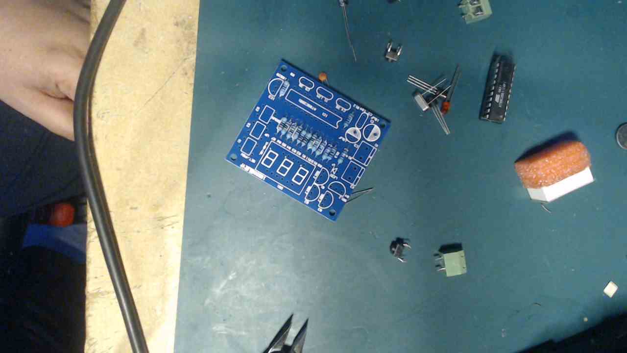
Watch the polarity of the LED, electrolytic capacitors and also look at the PCB markings to insert the DS18B20 and transistors the correct way. Make sure you identify the DS18B20 from the 4 transistors as they will look similar, you can verify the parts by the markings.
You have to be careful
Purchase
Just over $6 is not bad for a kit like this to be fair
| ICSTation | $6.01 |
Summary
A pretty low price for the kit, as stated its easy enough to assemble and is actually pretty useful
The downside for me is no source code for the microcontroller – its pre-programmed. If this was available and you can review it and even possible change it and upload to your microcontroller then that would be great and you could have called this a microcontroller learning kit.
Also if the micro gets damaged then you have no way of getting the kit working.
I would give it a rating of 7 out of 10 for a basic kit, if it had the code it would have gone up to maybe a 9