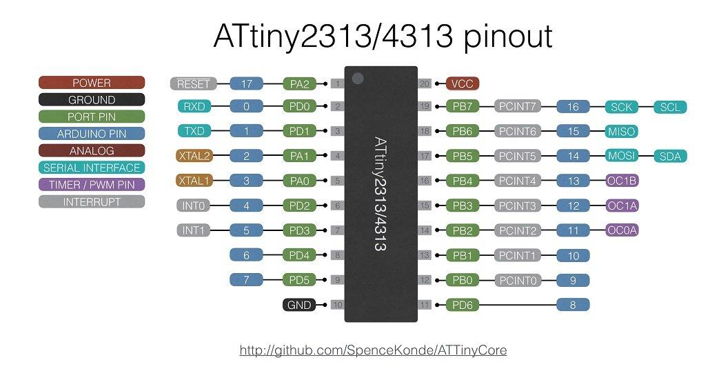
This is the second part of setting up an Arduino to program an Attiny microcontroller, in the previous parts we added support for the variety of microcontrollers. For reference purposes this is what the Attiny2313 will be like when you do this, the pins and the corresponding Arduino pins are shown below, as you can see you still get 16 I/O pins, I2C capabilities, 3 PWM pins and a serial interface for communications.
You will need to add support for the ATtiny2313 as per Programming ATtiny85 with Arduino Uno but you need to add the following
http://drazzy.com/package_drazzy.com_index.json
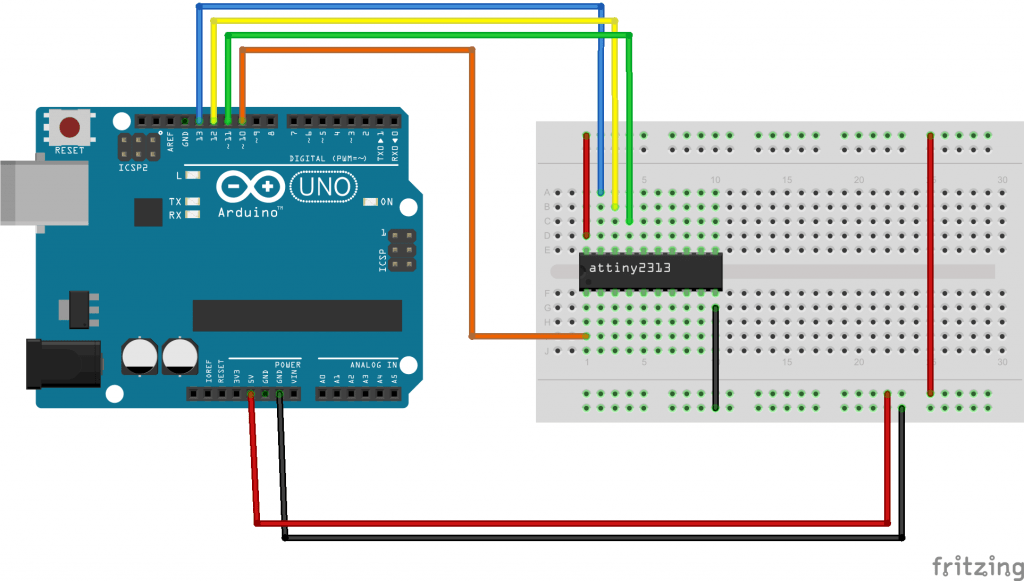
Setup attiny2313 connection with Arduino board
Connect up your Attiny2313 to your Arduino as follows
1) attiny2313 pin 1 to arduino pin 10 reset
2) attiny 2313 pin 17 to arduino pin 11 MOSI
3) attiny2313 pin 18 to arduino pin 12 MISO
4) attiny2313 pin 19 to arduino pin 13 SCK
5) attiny2313 pin 10 to arduino GND
6) attiny2313 pin 20 to arduino VCC
Layout
The diagram does not show the LED we connected to test with, this was connected to pin 7.
Steps
Open the ArduinoISP program and upload the ArduinoISP program to the Arduino board to turn it into an ISP programmer.
1) Open ArduinoISP program.
File>Examples>ArduinoISP
2) Select the serial port.
Tools>Port>COMX (enter your com port here)
2) Select the required Arduino board, in this case we are using an Arduino Uno.
Tools>Board>Arduino Uno
3) Set the programmer type as AVRISP MKII.
Tools>Programmer>AVRISP MKII
4) Press the upload button.
5) Now your Arduino Uno is setup as the ISP programmer. Now to setup your Arduino to program your Attiny with a modified blink example
6) Select the AVR target for the Arduino ISP to program to.
Tools>Board>ATtinyx313
7) Change the Board for the Arduino ISP to program to.
Tools>Chip>ATtiny2313
8) Make sure the Clock for the Arduino ISP is set to 8Mhz.
Tools>Clock>8mhz(internal)
You can see these settings in the screenshot below
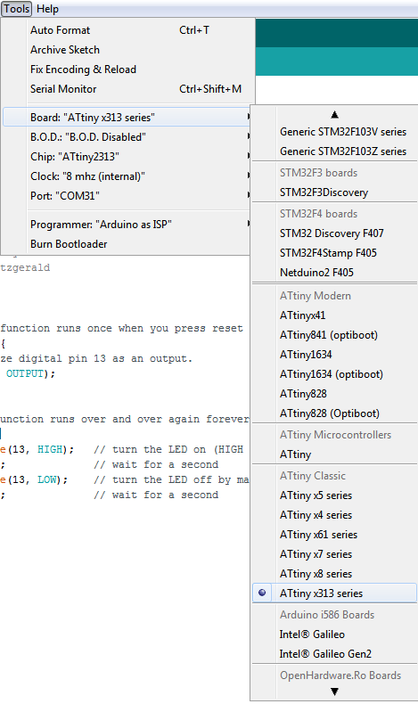
9) Set the programmer mode.
Tools>Programmer>Arduino as ISP
10) Finally, start the sketch upload to the Attiny2313 microcontroller
File>Upload
This is our code example to upload
[codesyntax lang=”cpp”]
// the setup function runs once when you press reset or power the board
void setup() {
  // initialize digital pin 13 as an output.
  pinMode(7, OUTPUT);
}

// the loop function runs over and over again forever
void loop() {
  digitalWrite(7, HIGH);   // turn the LED on (HIGH is the voltage level)
  delay(1000);              // wait for a second
  digitalWrite(7, LOW);    // turn the LED off by making the voltage LOW
  delay(1000);              // wait for a second
}
[/codesyntax]
If you connect an LED to pin 7 of your Attiny2313 you will see an LED flash on and off but it seems a bit slow
If you want you can Burn the Bootloader to the Attiny and the microcontroller will run at 8Mhz and the example above the led will flash on and off at the correct speed