In this article we look at an AT89C2051 Chip Electronic Alarm Clock kit that you can build which you has the following features create a clock, time set, alarm set, countdown timer, stopwatch, counter, hourly chime, precise time display, and 24 hours format.
This is an image of the completed board
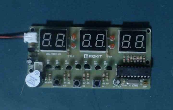
AT89C2051 Chip Electronic Alarm Clock Kit completed
This is the kit you get
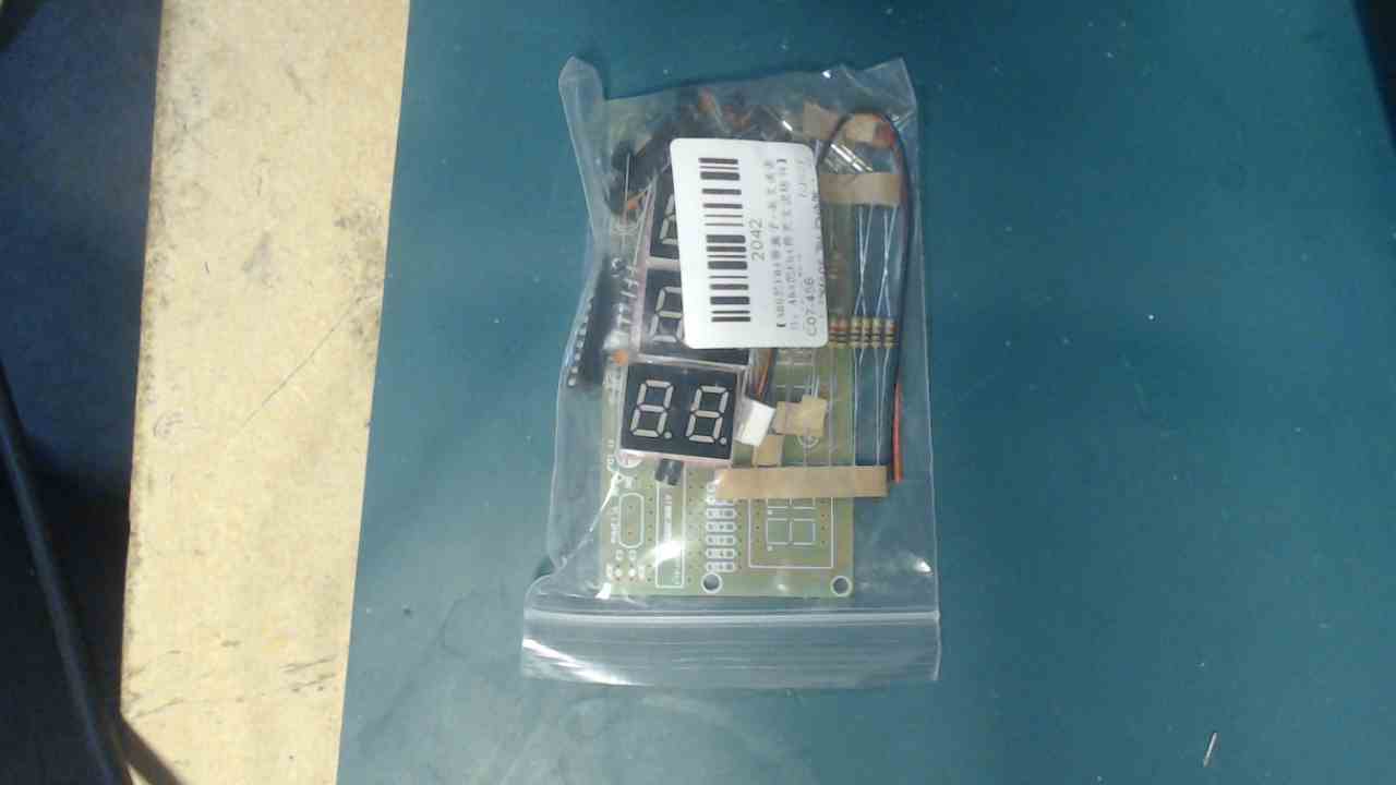
AT89C2051 Chip Electronic Alarm Clock Kit bagged
Specs
The operating voltage is DC 7V – 12V so ideally a 9v battery can be used, pay attention to the polarity when connecting to the power supply.
During operation, continuous short time (less than one second) press S3, you can make a continuous cycle option in the following six functions.
Meanwhile for a long press (more than 2 seconds) press S3, then return to the clock function model immediately.
1. Clock function: display 10:10:00 after connect to power
2. Correcting function: Press the S3 button once, namely with the flashing current time and the colon status, after that press the S2 button advances the hours by one , pressing the S1 button means advancing the minutes by 1, seconds are not adjustable .
3. Alarm function: Press the S3 button twice , the display status is 22:10:00. Then press S2 button means advances the hours by one pressing the S1 button means advancing the minutes by 1, seconds are not adjustable . When the hours are more than 23 the screen will be displayed – : – : – , this means close the alarm function.
4. Countdown function : Press the S3 button three times, shows a status of 0 , colon as long off. Press the S2 button then from low so high to display, press S1 button means plus 1, when press S2 button to the six times it will begin to countdown based on the time you set up, press S2 button again will re-enter the adjustment function, and stop the countdown .
5. Stopwatch function : Press the S3 button four times, with display status of 00:00:00 , colon as long bright . Stopwatch is started by pressing the S2 button , when the S2 button is pressed again to end the stopwatch, after you finish the stopwatch, you can press the S1 button and the display is cleared.
6. Counter function : Press the S3 button five times, with the displays status of 00:00:00 , the colon is long off, the counter is incremented 1 by pressing S2 button, press S1 button again the counter is cleared .
Schematic
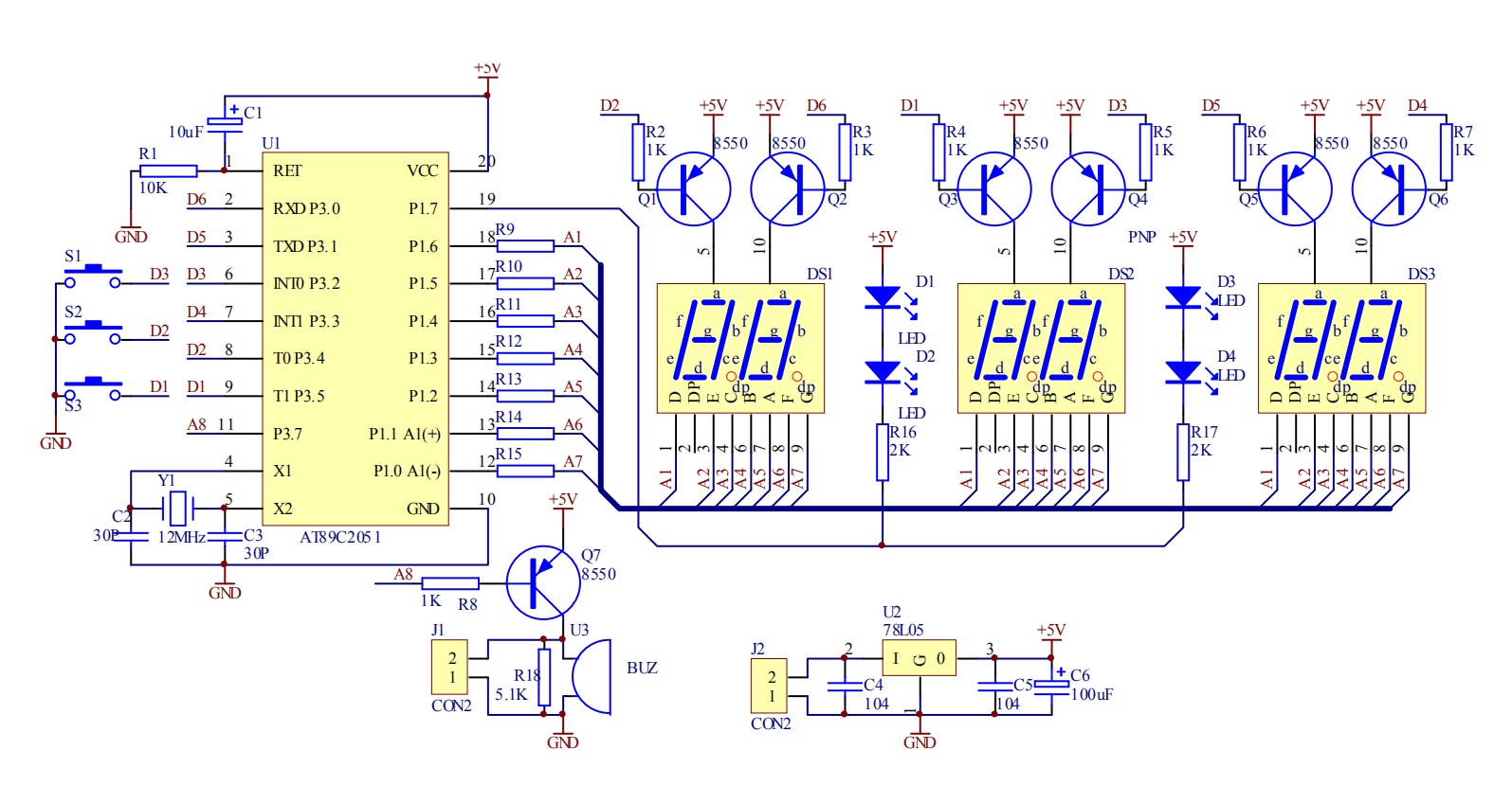
C51 Digital Electronic Clock schematic
Parts List
| Part | Quantity | PCB code |
| 1k resistor | 14 | R2 – R8 R9 – R15 |
| 2k resistor | 2 | R16 – R17 |
| 5.1k resistor | 1 | R18 |
| 10k resistor | 1 | R1 |
| 30pf ceramic capacitor | 2 | C2 – C3 |
| 0.1uF ceramic capacitor | 2 | C4 – C5 |
| 10uF 25v electrolytic capacitor | 1 | C1 |
| 100uF 16v electrolytic capacitor | 1 | C6 |
| Red LEDs | 4 | D1 – D4 |
| 7 segment display | 3 | DS1 – DS3 |
| buzzer | 1 | U3 |
| S8550 transistor | 7 | Q1 – Q7 |
| AT89C2051 microcontroller | 1 | U1 |
| 78L05 voltage regulator | 1 | U2 |
| 12Mhz crystal | 1 | Y1 |
| push button switches | 3 | S1 – S3 |
| 2 pin vertical connector | 1 | J1 |
| 2 pin horizontal connector | 1 | J2 |
| 20 pin IC socket | 1 | U1 |
Start with the resistors, capacitors, crsytal and ic socket. Then the LEDs, transistors
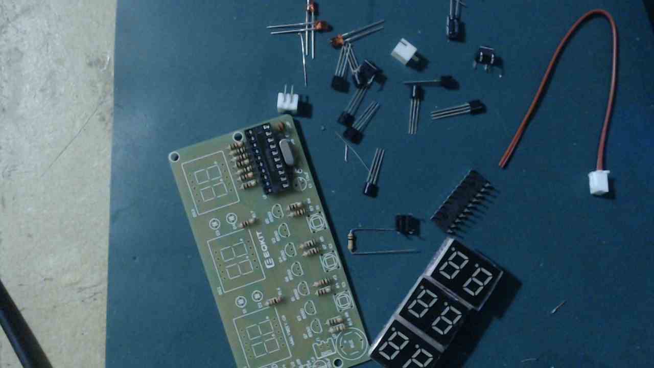
Watch the polarity of the LEDs, electrolytic capacitors, insert the transistors according to the pcb markings and be carefully add the microcontroller to the ic socket.
Purchase
A good price for this kit at only $6.29
| ICSTation | $6.29 |
Summary
A nice kit which has a few functions, it is easy to solder but again the microcontroller is already programmed and no code is supplied which is frustrating.
This is another 7 out of 10 kit but the ability to look at code and learn how it works would have boosted it to a 9