
How Zener Diodes Regulate Voltage
Most electronic components are designed to be far from breakdown conditions. Engineers normally make sure that transistors, capacitors and regular diodes are kept well within their limits so that they do not get damaged.
The Zener diode is not the same.
A Zener diode is designed to be on in reverse breakdown, unlike a regular diode which is designed to be off in reverse. In fact, it is the very uniqueness of its characteristic which makes it one of the simplest and most useful voltage-regulating devices in electronics.
For decades, zener diodes have been employed to stabilise voltages, safeguard sensitive circuits, generate reference voltages, and enhance the reliability of power supplies. Even in this age of sophisticated integrated circuits and switching regulators, Zener diodes are widely used because they are cheap, reliable, and surprisingly effective.
This is one of the most important principles in electronic circuit design and understanding how Zener diodes regulate voltage is very useful.
What Is a Zener Diode?
A Zener diode is a specially designed semiconductor diode intended to operate in reverse bias at a precisely defined voltage known as the Zener voltage.
Unlike ordinary diodes that are damaged if reverse voltage becomes excessive, a Zener diode is engineered to enter breakdown safely and repeatedly.
When reverse voltage reaches a specific value:
- The diode begins conducting
- Voltage remains nearly constant
- Excess current is safely diverted
This ability allows the diode to act as a simple voltage regulator.
Standard Diode vs Zener Diode
At first glance, a Zener diode looks very similar to an ordinary silicon diode.
Both devices:
- Conduct in forward bias
- Block current in reverse bias
- Are made from semiconductor materials
The major difference is their reverse-bias behavior.
Standard Silicon Diode
A conventional diode:
- Conducts forward current
- Blocks reverse current
- Is damaged if breakdown voltage is exceeded
Zener Diode
A Zener diode:
- Conducts forward current like a normal diode
- Blocks reverse current below its rated voltage
- Conducts safely when breakdown voltage is reached
This special breakdown region is where voltage regulation occurs.
Understanding Reverse Bias
To understand Zener regulation, it helps to review reverse bias.
In reverse bias:
- Positive voltage is connected to the cathode
- Negative voltage is connected to the anode
Under normal conditions:
- Only tiny leakage currents flow
- The diode appears almost like an open switch
As voltage increases, eventually the breakdown voltage is reached.
For ordinary diodes, this is dangerous.
For Zener diodes, it is normal operation.
What Is Zener Breakdown?
Zener breakdown occurs when the electric field across the semiconductor junction becomes strong enough to allow current flow despite reverse bias.
Once breakdown begins:
- Current increases dramatically
- Voltage remains nearly constant
- The diode regulates voltage
This characteristic forms the basis of Zener voltage regulation.
A typical Zener diode might be rated at:
- 3.3V
- 5.1V
- 9.1V
- 12V
- 24V
When reverse voltage reaches that value, the diode starts conducting.
The Voltage Regulation Principle
The key feature of a Zener diode is that its voltage remains almost constant over a wide current range.
For example, consider a 5.1V Zener diode.
Once breakdown begins:
- Input voltage may vary
- Load current may vary
- Zener current may vary
Yet the diode maintains approximately:
V_Z\approx5.1V
This makes it useful as a simple voltage reference.
A Basic Zener Regulator Circuit
The most common circuit consists of:
- Input voltage source
- Series resistor
- Zener diode
- Load
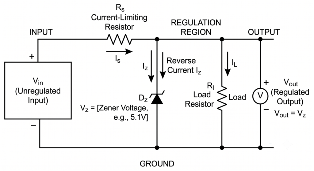
The resistor limits current while the Zener maintains a stable output voltage.
Despite its simplicity, this circuit can provide surprisingly good regulation.
Why the Series Resistor Is Essential
A common beginner mistake is assuming the Zener diode alone regulates voltage.
The resistor performs a critical function.
Without the resistor:
- Current would rise uncontrollably
- The diode could overheat
- Failure could occur rapidly
The resistor absorbs excess voltage and limits current to safe levels.
Together, the resistor and Zener diode form a complete voltage-regulating system.
How Regulation Actually Works
Imagine a 12V supply feeding a 5.1V Zener regulator.
Initially:
- Voltage rises
- Breakdown begins at 5.1V
Once breakdown starts:
- Extra current flows through the Zener
- Output remains near 5.1V
If supply voltage increases:
- Zener current increases
- Output voltage changes very little
If supply voltage decreases:
- Zener current decreases
- Output voltage remains relatively stable
This automatic adjustment creates regulation.
Understanding Zener Current
A Zener diode only regulates properly when sufficient current flows through it.
Three operating regions exist.
Below Breakdown
- Current is minimal
- Regulation does not occur
Regulation Region
- Proper breakdown occurs
- Voltage remains stable
- Normal operation
Excessive Current Region
- Device overheats
- Power dissipation becomes excessive
- Failure may occur
Designers must ensure operation remains within the regulation region.
Zener Voltage Ratings
Manufacturers produce Zener diodes with many voltage ratings.
Common examples include:
| Zener Voltage | Typical Use |
|---|---|
| 3.3V | Logic circuits |
| 5.1V | Voltage references |
| 6.8V | Power supplies |
| 9.1V | Protection circuits |
| 12V | Automotive electronics |
| 24V | Industrial systems |
The chosen voltage depends entirely on the application.
Why 5.1V Zeners Are Popular
Among all Zener voltages, 5.1V devices are especially common.
One reason is temperature stability.
Around 5.1V:
- Zener effects and avalanche effects balance
- Temperature drift is minimized
- Voltage remains more stable
As a result, many precision reference circuits use 5.1V Zener diodes.
Zener Breakdown vs Avalanche Breakdown
Two mechanisms can cause reverse conduction.
Zener Breakdown
Occurs at relatively low voltages.
Typically below:
5V to 6V
Strong electric fields pull electrons across the junction.
Avalanche Breakdown
Occurs at higher voltages.
Typically above:
6V
Electrons collide with atoms and create additional charge carriers.
In practice, most commercial Zener diodes use a combination of both effects.
Zener Diodes as Voltage References
Many circuits need a stable reference voltage.
Examples include:
- Analog measurement systems
- ADC reference circuits
- Power supply feedback loops
- Precision sensors
A Zener diode provides a simple and inexpensive reference source.
Even when supply voltage fluctuates, the reference remains relatively constant.
Protecting Circuits from Overvoltage
Zener diodes are frequently used for protection.
Suppose a microcontroller input can tolerate only 5V.
A Zener diode can clamp excessive voltages.
Normal operation:
- Input below 5V
- Zener remains inactive
Fault condition:
- Voltage exceeds 5.1V
- Zener conducts
- Excess energy is diverted
This helps protect sensitive electronics.
Protecting Microcontroller Inputs
Popular platforms such as:
- Arduino
- ESP32
- STM32
- Raspberry Pi Pico
often include voltage protection circuitry.
Zener diodes may be used to prevent accidental overvoltage damage on GPIO pins or communication lines.
Zener Diodes in Power Supplies
Before modern regulator ICs became widespread, Zener regulators were extremely common.
They were used to create:
- Stable DC rails
- Reference voltages
- Bias supplies
Although integrated regulators now dominate many applications, Zener-based regulators still appear in low-cost and low-current designs.
Zener Diodes in Automotive Electronics
Vehicle electrical systems experience:
- Voltage spikes
- Alternator fluctuations
- Load dump events
Zener diodes help protect:
- Sensors
- Control modules
- Communication circuits
from excessive voltages.
Power Dissipation Considerations
Like any component, Zener diodes have limits.
Power dissipation equals:
P=V_Z\times I_Z
Where:
- P = Power
- VZ = Zener voltage
- IZ = Zener current
For example:
- VZ = 5.1V
- IZ = 20mA
Power dissipated:
0.102W
A suitable power rating must always be chosen.
Common Zener Power Ratings
Popular ratings include:
| Rating | Typical Package |
|---|---|
| 250mW | Small signal |
| 500mW | General purpose |
| 1W | Power applications |
| 5W | Heavy-duty regulation |
| 10W+ | Industrial protection |
Higher power ratings allow greater current handling.
Common Beginner Mistakes
Connecting the Diode the Wrong Way
A Zener regulator operates in reverse bias.
Many beginners install the diode like a standard rectifier diode and wonder why regulation does not occur.
Forgetting the Series Resistor
This is one of the most common errors.
Without current limiting:
- Excessive current flows
- Device overheats
- Failure occurs
Ignoring Power Dissipation
Voltage regulation creates heat.
Power ratings must never be exceeded.
Assuming Perfect Regulation
Zener diodes provide good regulation but not perfect regulation.
Output voltage varies slightly with:
- Current
- Temperature
- Manufacturing tolerances
Zener Diodes vs Voltage Regulator ICs
| Feature | Zener Diode | Regulator IC |
|---|---|---|
| Cost | Very Low | Low |
| Complexity | Simple | Moderate |
| Accuracy | Moderate | High |
| Efficiency | Low | Higher |
| Current Capability | Limited | Higher |
| Component Count | Minimal | More Components |
Modern regulator ICs generally provide better performance, but Zener diodes remain useful for simple applications.
Common Zener Diode Part Numbers
Frequently encountered devices include:
- BZX55 series
- BZX79 series
- 1N4728A
- 1N4733A
- 1N4742A
- 1N4749A
These are widely available and commonly used in educational and practical circuits.
Where You Will Find Zener Diodes
Zener diodes appear in:
- Power supplies
- Embedded systems
- Industrial controls
- Battery chargers
- Automotive electronics
- Sensor interfaces
- Communication equipment
- Voltage monitoring circuits
Despite their age, they remain one of the most versatile protection and regulation components in electronics.
Conclusion
Zener diodes regulate voltage by operating safely in reverse breakdown mode. Once their rated Zener voltage is reached, they conduct current while maintaining a nearly constant voltage across their terminals. Combined with a current-limiting resistor, they provide a simple and reliable method of voltage regulation.
Although modern regulator ICs often offer better efficiency and precision, Zener diodes remain indispensable for voltage references, overvoltage protection, signal clamping, and low-cost power supply designs. Their simplicity, reliability, and effectiveness ensure they continue to play an important role in modern electronics.