
NPN vs PNP Transistors
Transistors are among the most important components in electronics. From simple LED circuits to complex industrial control systems, transistors act as electronic switches and amplifiers that make modern technology possible.
For beginners, one of the first concepts encountered is the distinction between NPN and PNP transistors. At first glance they appear nearly identical, but their operating principles, current flow directions, and switching methods differ significantly.
Understanding these differences is essential for designing circuits, troubleshooting electronic systems, and working with microcontrollers such as Arduino, ESP32, Raspberry Pi Pico, STM32, and countless other platforms.
What Is a Bipolar Junction Transistor (BJT)?
NPN and PNP transistors belong to a family called Bipolar Junction Transistors, commonly abbreviated as BJTs.
A BJT has three terminals:
- Base (B)
- Collector (C)
- Emitter (E)
The transistor uses a small current flowing into or out of the base to control a much larger current flowing between the collector and emitter.
This allows a tiny control signal to switch or amplify larger loads.
The Meaning of NPN and PNP
The names describe the arrangement of semiconductor materials inside the transistor.
NPN Structure
An NPN transistor consists of:
- N-type semiconductor
- P-type semiconductor
- N-type semiconductor
Hence the name:
N - P - N
PNP Structure
A PNP transistor consists of:
- P-type semiconductor
- N-type semiconductor
- P-type semiconductor
Hence:
P - N - P
Although the internal structure differs, both devices perform similar switching and amplification tasks.
Visual Symbols
NPN Symbol
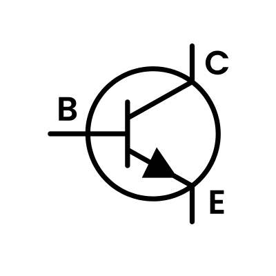
The emitter arrow points outward.
A useful memory trick is:
NPN = Not Pointing iN
The arrow points away from the transistor.
PNP Symbol
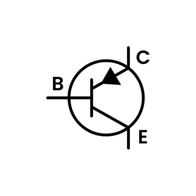
The emitter arrow points inward toward the transistor.
Understanding Current Flow
One of the most important differences involves current direction.
NPN Current Flow
Conventional current flows:
Collector → Emitter
when the transistor is switched on.
Electrons actually move in the opposite direction, but conventional current flow remains the standard used in circuit diagrams.
PNP Current Flow
Conventional current flows:
Emitter → Collector
when conducting.
This reversal influences how each transistor is driven.
How an NPN Transistor Works
NPN transistors are the most commonly used transistor type in electronics.
To turn an NPN transistor on:
- Base voltage must be higher than emitter voltage
- Typically about 0.7V higher
The base-emitter junction behaves similarly to a diode.
Example
Assume:
- Emitter = 0V
- Base = 0.7V
The transistor begins conducting.
If:
- Base = 5V
- Emitter = 0V
The transistor turns fully on and allows collector current to flow.
This makes NPN devices ideal for microcontroller-controlled switching.
How a PNP Transistor Works
PNP transistors operate in the opposite manner.
To turn a PNP transistor on:
- Base voltage must be lower than emitter voltage
Typically:
- Emitter = +5V
- Base = +4.3V
The transistor conducts.
If the base rises to the same voltage as the emitter, conduction stops.
This reverse control arrangement often confuses beginners.
Comparing Switching Logic
NPN
| Base Signal | State |
|---|---|
| High | ON |
| Low | OFF |
PNP
| Base Signal | State |
|---|---|
| Low | ON |
| High | OFF |
This opposite behavior is one of the most important practical differences.
Low-Side Switching with NPN Transistors
NPN transistors are frequently used for low-side switching.
The load connects between the supply voltage and transistor.
+12V
  |
 LOAD
  |
Collector
 NPN
Emitter
  |
 GND
When the transistor turns on:
- Current flows through the load
- Current reaches ground
- Load activates
This configuration is extremely common.
Examples include:
- Relays
- LEDs
- Solenoids
- Motors
- Buzzers
High-Side Switching with PNP Transistors
PNP transistors often perform high-side switching.
+12V
  |
Emitter
 PNP
Collector
  |
 LOAD
  |
 GND
When activated:
- Current flows from the supply
- Through the transistor
- Into the load
This allows switching on the positive side of a circuit.
Why NPN Transistors Are More Common
NPN transistors dominate most electronic designs.
Several factors contribute to this popularity.
Faster Operation
Electrons move more efficiently than holes within semiconductor materials.
Because NPN devices primarily rely on electron flow:
- Faster switching
- Better high-frequency performance
are often achieved.
Easier Microcontroller Interface
Microcontrollers naturally produce positive voltages.
An NPN transistor turns on when its base receives a positive signal.
This makes interfacing straightforward.
Wider Availability
Many popular transistor families are NPN:
- 2N2222
- BC547
- PN2222
- TIP120
- BD139
They are inexpensive and widely stocked.
Common PNP Transistors
Popular PNP devices include:
- BC557
- 2N2907
- TIP125
- BD140
- S8550
They are often paired with complementary NPN devices.
For example:
| NPN | PNP |
|---|---|
| BC547 | BC557 |
| BD139 | BD140 |
| TIP120 | TIP125 |
Understanding Transistor Gain
Transistors amplify current.
Current gain is represented by:
hFE
or:
β
The relationship is:
I_C=\beta I_B
Where:
- IC = Collector current
- IB = Base current
- β = Gain
For example:
- Base current = 2mA
- Gain = 100
Collector current could theoretically reach:
200mA
provided other operating conditions are satisfied.
Saturation Mode
When used as switches, transistors usually operate in saturation.
In saturation:
- Fully ON
- Minimum voltage drop
- Lowest power dissipation
This state is preferred for switching applications.
Active Region
When used as amplifiers, transistors operate in the active region.
In this mode:
- Output current follows input current
- Amplification occurs
- Linear operation is maintained
Audio amplifiers commonly use transistors in this region.
Darlington Transistors
Some devices combine two transistors internally.
Examples:
- TIP120 (NPN)
- TIP125 (PNP)
Advantages:
- Very high gain
- Simple drive requirements
Disadvantages:
- Larger voltage drop
- Slower switching
They remain popular in hobby projects.
Typical Microcontroller Example
Suppose an ESP32 controls a 12V relay.
The GPIO cannot safely supply relay current directly.
An NPN transistor solves the problem.
Circuit:
ESP32 GPIO
      |
   Resistor
      |
     Base
      |
    NPN
      |
 Relay
      |
    +12V
The transistor handles relay current while the ESP32 only supplies a small base current.
This is one of the most common transistor applications in embedded electronics.
Common Beginner Mistakes
Reversing Collector and Emitter
Many transistor packages look similar.
Always check the datasheet.
Pinouts vary significantly.
Forgetting Base Resistors
Connecting a microcontroller directly to a transistor base can cause excessive current.
A resistor is usually required.
Assuming All Transistors Are Identical
Different devices have different:
- Current ratings
- Voltage ratings
- Gain values
- Switching speeds
Always verify specifications.
Ignoring Flyback Diodes
When switching:
- Relays
- Solenoids
- Motors
a flyback diode is essential.
Without it, voltage spikes can destroy the transistor.
NPN vs PNP Comparison Table
| Feature | NPN | PNP |
|---|---|---|
| Turns On With | Positive base voltage | Lower base voltage |
| Current Flow | Collector to emitter | Emitter to collector |
| Switching Type | Low-side | High-side |
| Speed | Generally faster | Slightly slower |
| Popularity | Very common | Less common |
| Microcontroller Interface | Easy | More complex |
| Typical Use | Relays, LEDs, motors | High-side power switching |
Where NPN and PNP Work Together
Many circuits use both transistor types.
Examples include:
- Audio amplifiers
- Push-pull output stages
- Motor drivers
- Power supplies
- H-bridge circuits
Using complementary transistor pairs allows designers to switch both positive and negative portions of a signal efficiently.
The Rise of MOSFETs
While BJTs remain important, many modern designs now use MOSFETs.
Advantages include:
- Higher efficiency
- Lower drive current
- Faster switching
- Better high-current capability
However, BJTs remain valuable because they are:
- Inexpensive
- Easy to understand
- Widely available
- Excellent for learning electronics
Conclusion
NPN and PNP transistors perform similar functions but operate with opposite current and voltage relationships. NPN transistors turn on when the base is driven positive relative to the emitter, while PNP transistors turn on when the base is pulled lower than the emitter.
NPN devices dominate modern electronics because they are easier to drive from microcontrollers and generally offer better performance. PNP transistors remain essential for high-side switching and complementary circuit designs. Understanding how both operate provides a solid foundation for designing, troubleshooting, and improving electronic circuits of all types.