A photoresistor (or light-dependent resistor, LDR, or photocell) is a light-controlled variable resistor. The resistance of a photoresistor decreases with increasing incident light intensity; in other words, it exhibits photoconductivity. A photoresistor can be applied in light-sensitive detector circuits, and light- and dark-activated switching circuits.
A photoresistor is made of a high resistance semiconductor. In the dark, a photoresistor can have a resistance as high as several megohms (MΩ), while in the light, a photoresistor can have a resistance as low as a few hundred ohms. If incident light on a photoresistor exceeds a certain frequency, photons absorbed by the semiconductor give bound electrons enough energy to jump into the conduction band. The resulting free electrons (and their hole partners) conduct electricity, thereby lowering resistance. The resistance range and sensitivity of a photoresistor can substantially differ among dissimilar devices. Moreover, unique photoresistors may react substantially differently to photons within certain wavelength bands.
A photoelectric device can be either intrinsic or extrinsic. An intrinsic semiconductor has its own charge carriers and is not an efficient semiconductor, for example, silicon. In intrinsic devices the only available electrons are in the valence band, and hence the photon must have enough energy to excite the electron across the entire bandgap. Extrinsic devices have impurities, also called dopants, added whose ground state energy is closer to the conduction band; since the electrons do not have as far to jump, lower energy photons (that is, longer wavelengths and lower frequencies) are sufficient to trigger the device. If a sample of silicon has some of its atoms replaced by phosphorus atoms (impurities), there will be extra electrons available for conduction. This is an example of an extrinsic semiconductor
These devices are quite easy to work with, you will see in the schematic later that tyou simply need an LDR and a resistor, here is a picture of a basic module
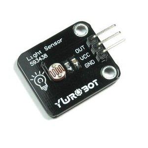
ldr module
Parts List
1 x LDR
1 x 10k resistor
1 x Arduino
1 x Breadboard
Some connecting cables
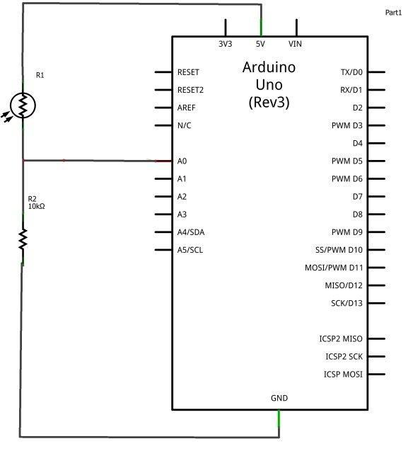
Schematics
Lets look at how we would connect an LDR to an Arduino
Code
The arduino, with its inbuilt ADC (Analog to Digital Converter) then converts the analog voltage (from 0-5V) into a digital value in the range of (0-1023).
In this example we output the reading via the serial port. You can monitor this in the Serial Port Monitor, Tools – Serial Monitor in the IDE
[codesyntax lang=”cpp”]
int sensorValue;

void setup()
{
 Serial.begin(9600); // starts the serial port at 9600
}

void loop()
{
 sensorValue = analogRead(0); // read analog input pin 0
 Serial.print(sensorValue, DEC); // prints the value read
 Serial.print(" \n"); // prints a space between the numbers
 delay(1000); // wait 1 second for next reading
}
[/codesyntax]
Now cover the LDR and shine a bright light at it to see the values change
Links
10PCS 5MM Photoresistor GL5528 GL5528 LDR Photo Resistors Light-Dependent 150V DC 100mW Newest