A Hall effect sensor is a transducer that varies its output voltage in response to a magnetic field. Hall effect sensors are used for proximity switching, positioning, speed detection, and current sensing applications.
In its simplest form, the sensor operates as an analog transducer, directly returning a voltage. With a known magnetic field, its distance from the Hall plate can be determined. Using groups of sensors, the relative position of the magnet can be deduced.
Frequently, a Hall sensor is combined with threshold detection so that it acts as and is called a switch. Commonly seen in industrial applications such as the pictured pneumatic cylinder, they are also used in consumer equipment; for example some computer printers use them to detect missing paper and open covers. When high reliability is required, they are used in keyboards.
Hall sensors are commonly used to time the speed of wheels and shafts, such as for internal combustion engine ignition timing, tachometers and anti-lock braking systems. They are used in brushless DC electric motors to detect the position of the permanent magnet.
A Hall effect sensor may operate as an electronic switch.
- Such a switch costs less than a mechanical switch and is much more reliable
- It can be operated up to 100 kHz.
- It does not suffer from contact bounce because a solid state switch with hysteresis is used rather than a mechanical contact.
- It will not be affected by environmental contaminants since the sensor is in a sealed package. Therefore, it can be used under severe conditions.
In the case of linear sensor (for the magnetic field strength measurements), a Hall effect sensor:
- can measure a wide range of magnetic fields
- is available that can measure either North or South pole magnetic fields
- can be flat
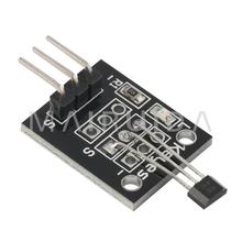
Lets look at an example of a module that is popularly used

The KY-003 is a Hall effect sensor. If no magnetic field is present, the signal line of the sensor is HIGH . If a magnetic field is presented to the sensor, the signal line goes LOW, at the same time the LED on the sensor lights up.
Schematics
Here is a breadboard and schematic layout created using parts in Fritzing
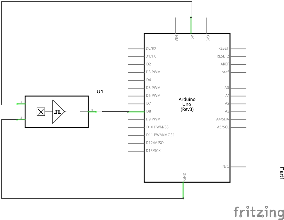
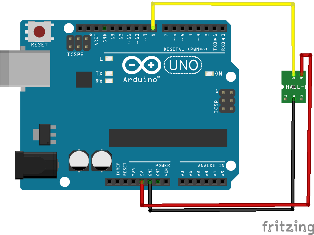
Connection
- Pin – is GND, connect to GND of the Arduino
- Middle pin is +5 v, connect to Arduino +5
- Pin S signal, connect to Arduino pin 8
You can use any Arduino input, we selected pin 8 for our example
Code
A fairly simple example here, there is a visual indication and also a debug option via the Serial Monitor in the Arduino IDE
[codesyntax lang=”cpp”]
int Led = 13 ; // Arduino built in LED
int SENSOR = 8 ; // define the Hall magnetic sensor
int val ; // define numeric variables

void setup ()
{
  Serial.begin(9600);
  pinMode (Led, OUTPUT) ;    // define LED as output
  pinMode (SENSOR, INPUT) ;  // define the Hall magnetic sensor line as input
}

void loop ()
{
  val = digitalRead (SENSOR) ; // read sensor line
  if (val == LOW) // when the Hall sensor detects a magnetic field, Arduino LED lights up
  {
    digitalWrite (Led, HIGH);
    Serial.println("Magnetic field detected");
  }
  else
  {
    digitalWrite (Led, LOW);
    Serial.println("No magnetic field detected");
  }
  delay(1000);
}
[/codesyntax]
Run the following and put a magnet near the hall effect sensor, the LED should go on and if you have the serial monitor open you will see an appropriate message displayed
Link
You can pick up the module for about $1
 Newest Hot Analog Hall Effect Magnetic Sensor Module 49E for AVR PIC New Arrivals Hot Selling