
How DIP Switches Work
In a world of touchscreens, software settings and cloud-based configuration, it’s easy to forget some of the simplest components in electronics. However, a lot of equipment still uses a surprisingly old but very effective technology for configuration and setup: the DIP switch.
For decades DIP switches have been used to configure electronic equipment without the need for software, keyboards, displays or communication interfaces. They’re still widely found in industrial controllers, networking gear, development boards, security systems, instrumentation, and embedded electronics because they offer a straightforward, reliable, and inexpensive way to change operating parameters.
DIP switches are simple but play an important role in many electronic products. Understanding how they work gives insight into how engineers build configurable systems that are easy to maintain and deploy.
What Is a DIP Switch?
A DIP switch is a small set of manually operated electrical switches packaged in a standard housing.
The name DIP stands for:
Dual In-line Package
The term originates from the package style used by integrated circuits.
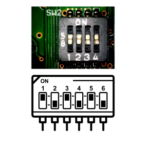
A typical DIP switch contains multiple miniature switches arranged in a row.
For example:
DIP Switch
Each switch can be individually set to:
- ON
- OFF
This allows binary configuration of electronic systems.
Why DIP Switches Were Developed
Before software-based configuration became common, electronic equipment still needed adjustable settings.
Examples included:
- Device addresses
- Communication speeds
- Operating modes
- Hardware options
DIP switches provided a simple solution.
Instead of rewriting firmware or modifying circuitry, users could simply move small switches into the desired positions.
This approach remains useful today.
Basic Construction
A DIP switch typically consists of:
- Plastic housing
- Multiple miniature switches
- Internal contacts
- External terminals
Each switch operates independently.
Internally, each switch simply opens or closes an electrical connection.
How a DIP Switch Works
At its core, a DIP switch behaves like a manual electrical switch.
OFF Position
OPEN CIRCUIT

----/ ----
Current cannot flow.
ON Position
CLOSED CIRCUIT

---------
Current can flow.
The electronics connected to the switch determine how this state is interpreted.
Understanding Binary Configuration
One reason DIP switches are so popular is their compatibility with binary numbers.
Each switch represents a binary digit:
| Position | Value |
|---|---|
| OFF | 0 |
| ON | 1 |
For example:
Switches

1 2 3 4

ON OFF ON OFF
becomes:
1010
in binary.
This allows many configuration options using only a few switches.
Why Binary Is Useful
Computers naturally work with binary values.
Each DIP switch provides a direct hardware representation of:
0
or
1
This allows microcontrollers and logic circuits to read switch settings easily.
How Many Settings Are Possible?
The number of configurations depends on the number of switches.
Formula:
Configurations=2^N
Where:
- N = Number of switches
Examples:
| Switches | Configurations |
|---|---|
| 2 | 4 |
| 4 | 16 |
| 8 | 256 |
| 10 | 1024 |
Even a small DIP switch bank can provide many setup options.
Common DIP Switch Sizes
Typical DIP switch packages include:
- 2-position
- 4-position
- 6-position
- 8-position
- 10-position
- 12-position
Eight-position switches are particularly common.
Slide-Type DIP Switches
The most familiar design uses tiny sliding actuators.
Example:
1 2 3 4

ON
| | | |
[ ][ ][ ][ ]
The switch is moved using:
- Fingernail
- Small screwdriver
- Tweezers
These designs are inexpensive and reliable.
Piano-Type DIP Switches
Another common style resembles miniature piano keys.
Each switch is pressed:
- Down for ON
- Up for OFF
Advantages include:
- Easier operation
- Better visibility
These are often used in industrial equipment.
Rotary DIP Switches
Some systems use rotary DIP switches.
Instead of multiple individual switches:
- A rotating dial selects values
Common options include:
0–9
0–15
Rotary DIP switches are popular for setting addresses and device IDs.
DIP Switches and Pull-Up Resistors
A DIP switch rarely connects directly to a microcontroller input.
Instead, pull-up or pull-down resistors are usually employed.
Example:
3.3V
 |
Resistor
 |
 +---- Input Pin
 |
Switch
 |
GND
This arrangement ensures the input always has a valid logic level.
Without these resistors:
- Inputs may float
- Unpredictable readings occur
Reading DIP Switches with a Microcontroller
Platforms such as:
- Arduino
- ESP32
- STM32
- Raspberry Pi Pico
can easily read DIP switch settings.
Software simply reads each input pin:
if (digitalRead(pin) == HIGH)
{
   // Switch ON
}
The resulting binary value can determine system behavior.
Device Address Selection
One of the most common uses is assigning device addresses.
Examples include:
- Industrial networks
- RS-485 devices
- Modbus controllers
- PLC modules
Suppose four switches are used:
0001 = Address 1
0010 = Address 2
0011 = Address 3
...
1111 = Address 15
Each device can be configured uniquely without changing firmware.
Communication Settings
DIP switches often configure communication parameters.
Examples include:
- Baud rate
- Parity
- Stop bits
- Protocol selection
Industrial equipment frequently uses this approach.
Industrial Automation Applications
Factories often prefer DIP switches because they:
- Require no software tools
- Are easy to inspect
- Remain reliable for years
Common uses include:
- Sensor configuration
- Controller setup
- Network addressing
- Safety systems
Many industrial devices still depend on DIP switches.
Networking Equipment
Older networking hardware commonly used DIP switches for:
- Address configuration
- Operating modes
- Speed selection
Although software configuration has become dominant, DIP switches remain common in specialized equipment.
Security Systems
Alarm panels and access control systems frequently use DIP switches.
They may configure:
- Device IDs
- Operating modes
- Zone assignments
Technicians can modify settings quickly in the field.
Embedded Development Boards
Some development boards include DIP switches to select:
- Boot modes
- Communication interfaces
- Voltage levels
- Peripheral options
This allows experimentation without firmware modifications.
FPGA and Logic Development
FPGA evaluation boards often contain DIP switches because they provide simple user inputs.
Students and engineers can:
- Test logic designs
- Create binary inputs
- Simulate hardware controls
without adding external circuitry.
Advantages of DIP Switches
Simplicity
No software is required.
Reliability
Mechanical operation is straightforward and proven.
Low Cost
Extremely inexpensive.
Easy Troubleshooting
Settings are visible immediately.
Non-Volatile
Configuration remains unchanged when power is removed.
Limitations of DIP Switches
Manual Configuration
Settings must be changed physically.
Limited Number of Options
Large numbers of settings require many switches.
Mechanical Wear
Repeated operation can eventually wear contacts.
Human Error
Incorrect switch positions can cause configuration mistakes.
DIP Switches vs Jumpers
Jumpers are another common configuration method.
| Feature | DIP Switch | Jumper |
|---|---|---|
| Ease of Adjustment | High | Lower |
| Visibility | Excellent | Moderate |
| Tool Requirement | Usually None | Often Needed |
| Reusability | Excellent | Good |
| Configuration Speed | Fast | Slower |
DIP switches are generally more user-friendly.
DIP Switches vs Software Configuration
| Feature | DIP Switch | Software |
|---|---|---|
| Power Required | No | Yes |
| Visibility | Immediate | Requires Interface |
| Security | Physical Access Required | Potentially Remote |
| Flexibility | Limited | High |
| Reliability | High | Depends on Software |
Many systems combine both methods.
Common Beginner Mistakes
Reading the ON Label Incorrectly
Different manufacturers may orient switches differently.
Always check markings carefully.
Forgetting Pull-Up Resistors
Floating inputs can produce unpredictable results.
Misinterpreting Binary Values
Switch numbering and bit order matter.
Changing Settings While Powered
Some equipment only reads switch states during startup.
A reboot may be required.
Typical Electrical Ratings
Most DIP switches are intended for signal-level switching.
Typical ratings include:
- 24V DC
- 25mA–100mA
They are not designed for switching large loads directly.
Where You Will Find DIP Switches
DIP switches appear in:
- PLC systems
- Industrial controllers
- Alarm systems
- Communication equipment
- Test instruments
- FPGA boards
- Development kits
- HVAC systems
- Security hardware
- Embedded products
Despite their age, they remain surprisingly common.
Why DIP Switches Remain Relevant
Many modern technologies eventually disappear as software replaces hardware.
DIP switches are different.
Engineers continue using them because they provide:
- Immediate visibility
- Hardware-level configuration
- Reliability
- Simplicity
In environments where dependable operation matters more than convenience, DIP switches remain difficult to replace.
Conclusion
DIP switches are simple yet very effective hardware configuration devices that allow electronic systems to be customised without software. They represent binary values using a series of tiny switches . These allow different functions such as address selection , setting up a communication , setting up operating modes , controlling hardware , etc .
DIP switches thrive in industrial automation, embedded electronics, networking equipment, security systems and development platforms, even as modern systems become increasingly dependent on software settings. Their simplicity, reliability, and ease of use make them an important component of electronic design.