4.3K
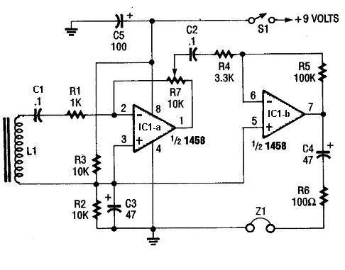
Audio signal tracer
As shown in the schematic above, when a inductor coil L1 is brought near the wire carrying the audio signal, the audio signal will be induced into the coil and the signal is fed to the inverting input of op-amp IC1-a. It is then amplified by and the amplified output is fed to IC1-b iverting input.
The second op-amp increases the signal level to drive a set of low impedance headphone, Z1.
The coil L1 is made by using a size #30 enamel coated copper wire wound on a 1.25 inch length of a 0.25 inch diameter ferrite rod. Use a turn of appoximately 80 to 100 turns. It can be located several feet from the circuit and connected it through a shielded cable.
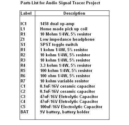
Audio signal tracer parts list
User submitted