
How SCR Thyristors Work
Before the advent of modern MOSFETs and IGBTs, engineers required a way to control large amounts of electrical power with relatively small control signals. One of the most important devices developed for this was the Silicon Controlled Rectifier which is more commonly known as the SCR.
SCRs are one of a family of devices called thyristors . They are still used in many industrial power control systems, motor drives, battery chargers, welding equipment, power supplies, and high voltage switching applications. Invented in the 1950s, they still play an important role wherever rugged, reliable and cost-effective power control is required.
By understanding the operation of SCR, one gains insight into one of the most influential semiconductor devices ever created and an explanation of the foundations of modern power electronics.
What Is an SCR?
An SCR (Silicon Controlled Rectifier) is a four-layer semiconductor switching device that can control large amounts of current using a relatively small gate signal.
Unlike an ordinary diode, which automatically conducts when forward biased, an SCR requires an additional trigger signal before it begins conducting.
Once triggered:
- Large currents can flow
- Device remains on
- Gate signal is no longer required
This unique behavior makes SCRs extremely useful for power control.
Why Is It Called a Silicon Controlled Rectifier?
The name describes the device’s operation:
Silicon
The semiconductor material used in construction.
Controlled
Conduction can be controlled using a gate signal.
Rectifier
Current primarily flows in one direction.
Together these characteristics create a controllable high-power switching device.
The Three SCR Terminals
Every SCR has three terminals:
A simplified symbol:
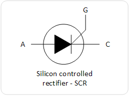
Each terminal performs a specific function.
Understanding the Anode and Cathode
The main current path flows between:
Anode
   ↓
Cathode
This path carries load current.
In many applications, the SCR may conduct:
- Several amps
- Tens of amps
- Hundreds of amps
depending on device specifications.
Understanding the Gate
The gate acts as the control terminal.
A small current applied to the gate can trigger the SCR into conduction.
Typical gate currents are far smaller than load currents.
For example:
Gate Current:
20mA

Load Current:
20A
This allows low-power circuits to control high-power loads.
Internal Structure of an SCR
An SCR contains four semiconductor layers arranged as:
P
N
P
N
This structure creates:
- Three PN junctions
- Complex switching behavior
- Latching characteristics
The four-layer arrangement distinguishes SCRs from ordinary diodes and transistors.
The Three Junctions
Inside the device are:
J1
J2
J3
These junctions determine whether the SCR is conducting or blocking current.
The behavior of these junctions changes depending on voltage and gate conditions.
Basic SCR Operation
An SCR operates in three primary states:
Reverse Blocking
Forward Blocking
Forward Conduction
Understanding these states is essential.
Reverse Blocking Mode
When reverse voltage is applied:
Cathode Positive
Anode Negative
the SCR blocks current.
It behaves similarly to a reverse-biased diode.
Only tiny leakage currents flow.
Forward Blocking Mode
When forward voltage is applied:
Anode Positive
Cathode Negative
the SCR still remains off.
This surprises many beginners.
Unlike a diode:
- Forward voltage alone is insufficient
- Gate trigger is required
The SCR blocks current despite being forward biased.
Forward Conduction Mode
When a gate pulse is applied:
- Internal switching occurs
- SCR turns on
- Current begins flowing
Once conduction starts:
- Device behaves almost like a closed switch
- Voltage drop becomes relatively small
- Large currents can flow
This is the SCR’s normal operating state.
The Triggering Process
Turning on an SCR involves:
- Applying forward voltage
- Supplying gate current
- Internal regenerative action begins
- Device latches on
- Current flows continuously
The process occurs extremely quickly.
Why SCRs Latch On
One of the most important SCR characteristics is latching.
Once triggered:
Gate signal can be removed
yet the SCR continues conducting.
This behavior differs from:
- MOSFETs
- BJTs
- IGBTs
which require continuous control.
Understanding Latching Action
The SCR can be modeled as two interconnected transistors.
A simplified representation:
PNP Transistor
      ↕
NPN Transistor
Each transistor reinforces the other.
Once conduction begins:
- Positive feedback develops
- Current sustains itself
- Device remains on
This regenerative action creates the latching effect.
Holding Current
An SCR will remain conducting as long as current stays above a minimum value called:
Holding Current
If current falls below this threshold:
- Regenerative action stops
- SCR turns off
- Device returns to blocking mode
Holding current is a critical specification.
Latching Current
Another important parameter is:
Latching Current
This is the minimum current required immediately after triggering to ensure the SCR remains on.
Latching current is typically higher than holding current.
How SCRs Turn Off
Unlike many modern transistors:
Gate cannot turn an SCR off.
This is one of the most important concepts to understand.
Once conducting, the SCR remains on until:
- Current falls below holding current
- External commutation occurs
SCRs in AC Circuits
AC power naturally crosses zero voltage and current.
At each half-cycle:
Current → 0
When current reaches zero:
- SCR turns off automatically
- Device becomes ready for the next trigger pulse
This characteristic makes SCRs extremely useful for AC power control.
Zero Crossing Behavior
For a 50Hz AC waveform:
100 Current Zero Crossings Per Second
For 60Hz:
120 Current Zero Crossings Per Second
Each crossing provides a natural turn-off opportunity.
Phase Angle Control
One of the most common SCR applications is phase angle control.
Instead of triggering immediately:
- Trigger timing is delayed
- Only part of the AC waveform reaches the load
This allows power regulation.
Phase Control Example
If the SCR triggers early:
Most of waveform delivered
High power reaches the load.
If the SCR triggers late:
Small portion delivered
Power is reduced.
This technique forms the basis of many power control systems.
Dimmer Switch Applications
Traditional light dimmers often use SCRs or TRIACs.
The controller:
- Delays triggering
- Adjusts delivered power
- Changes lamp brightness
The same principle applies to many AC power controllers.
Motor Speed Control
SCRs have long been used in motor drives.
Applications include:
- Industrial motors
- Conveyor systems
- Machine tools
- Process control equipment
By controlling average voltage, motor speed can be adjusted.
Battery Chargers
Industrial battery chargers frequently use SCRs.
Advantages include:
- High current capability
- Reliable operation
- Adjustable charging control
SCRs remain common in heavy-duty charging equipment.
Heating Control Systems
Electric heating systems often use SCR-based controllers.
Examples include:
- Industrial ovens
- Furnaces
- Plastic processing equipment
- Food production systems
SCRs allow precise power regulation.
Controlled Rectifiers
SCRs can be used in rectifier circuits.
Instead of fixed DC output:
- Trigger timing controls output voltage
- Adjustable DC becomes possible
These circuits are known as:
Controlled Rectifiers
and are widely used in industrial power electronics.
SCRs vs Ordinary Diodes
| Feature | SCR | Diode | | — | | | | Controlled Switching | Yes | No | | Gate Terminal | Yes | No | | Latching | Yes | No | | Power Control | Excellent | None | | Turn-On Control | User Controlled | Automatic |
SCRs provide far greater flexibility.
SCRs vs MOSFETs
| Feature | SCR | MOSFET | | — | | — | | Gate Turn-Off | No | Yes | | High Voltage Capability | Excellent | Good | | Cost | Low | Moderate | | AC Control | Excellent | Requires Additional Circuitry | | Switching Speed | Lower | Higher |
Both devices remain important depending on application requirements.
SCRs vs TRIACs
TRIACs evolved from SCR technology.
Key difference:
SCR
Conducts in one direction.
TRIAC
Conducts in both directions.
This makes TRIACs particularly useful for AC switching applications.
Advantages of SCRs
High Current Capability
Can control very large currents.
High Voltage Ratings
Suitable for industrial systems.
Rugged Construction
Excellent durability.
Low Cost
Economical for high-power applications.
Simple Triggering
Requires only a small gate current.
Limitations of SCRs
Cannot Be Turned Off Via Gate
Requires current interruption.
Slower Than MOSFETs
Not suitable for very high-frequency switching.
More Complex DC Turn-Off
Additional circuitry may be required.
Trigger Sensitivity
Improper triggering can cause problems.
Common Beginner Mistakes
Assuming the Gate Turns the SCR Off
This is perhaps the most common misconception.
Ignoring Holding Current
Current must fall below holding current for turn-off.
Treating SCRs Like Transistors
Their operation differs significantly.
Using Insufficient Gate Current
The device may fail to trigger reliably.
Forgetting Heat Dissipation
Large currents generate significant heat.
Typical SCR Specifications
Important parameters include:
- Maximum current
- Peak surge current
- Gate trigger current
- Holding current
- Latching current
- Reverse voltage rating
- Forward voltage rating
These values determine application suitability.
Where You Will Find SCRs
SCRs are used in:
- Motor drives
- Industrial automation
- Battery chargers
- Welding equipment
- Power supplies
- Heating controllers
- AC regulators
- Controlled rectifiers
- Soft starters
- High-power switching systems
Despite newer semiconductor technologies, SCRs remain common in industrial environments.
The Future of SCR Technology
MOSFETs and IGBTs dominate many modern applications, but SCRs continue to offer advantages where:
- Extremely high currents are involved
- Cost matters
- AC power control is required
- Ruggedness is essential
For these reasons, SCRs remain important components in industrial power electronics.
Conclusion
SCR thyristors are four-layer semiconductor devices that allow small gate signals to control large currents. Once triggered, they latch into conduction and remain on until current falls below a specified holding value. This unique behavior makes them particularly valuable for AC power control, industrial automation, motor drives, battery charging systems, and high-power switching applications.
Although newer technologies such as MOSFETs and IGBTs have become widespread, SCRs continue to provide reliable, cost-effective power control in many demanding environments. Their ability to handle high voltages and currents ensures they remain one of the most important devices in power electronics.